 |

| Quantity: | |
|---|---|
|
| |
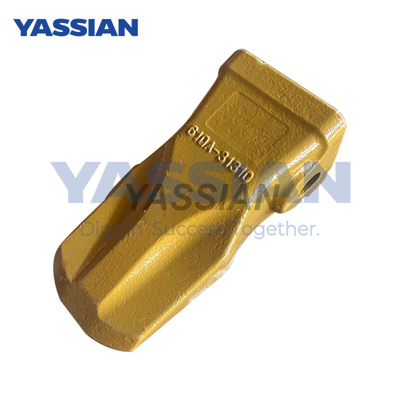
61QA-31310
YASSIAN or Your's


The difference between a drag sprocket and other components
The following is a detailed analysis of the differences between the drag sprocket and other core components (idler wheels, guide wheels, and drive wheels) in the track system of construction machinery, combined with a comprehensive comparison of functions, materials, and maintenance characteristics:
I. Differences in core functional positioning
Drag sprocket (supporting sprocket)
Function : Support the suspended sections of the branches on the tracks to prevent the tracks from sagging or derailing.
Position : Fixed on the inclined platform of the chassis X frame, located between the drive wheels and the guide wheels.
Motion characteristics : passive rotation, no power input, mainly subjected to vertical pressure.
Idler wheel
Function: : Support the weight of the equipment and distribute the pressure at the joint of the tracks.
Location : densely distributed along the track connection section (usually 6-10 on one side).
Motion characteristics : rotates along with the tracks and directly bears the load of the machine body.
Guide wheel
Function : Guide the track direction and coordinate with the tensioning device to adjust the tightness of the track.
Position : opposite to the drive wheels, located at the end of the track.
Drive wheel
Function : By meshing gears with track tracks, it provides walking power.
Position : Fixed at the output end of the walking motor, it must be at the rear of the equipment.
(Note: A schematic diagram of the component positions of the track system is inserted here to visually display the layout relationship among the four.)
⚙️ II. Structural and material differences
Key points of design for typical material structure characteristics of components
The 50Mn forged steel wheel body of the drag chain wheel is lightweight and has shallow grooves. The floating oil seal is dust-proof, shock-resistant and prevents mud and sand from getting stuck
The 40Mn2 alloy steel wheel body of the idler is thick and heavy, with deep grooves. Multiple sets of bearings support high load-bearing capacity and wear resistance
The cast steel or forged steel integrated tensioning cylinder of the guide wheel can be axially adjusted to dynamically calibrate the track tension
The high-strength alloy steel gear ring of the drive wheel is quenched, featuring high tooth profile accuracy, fatigue resistance and shear force resistance
(Note: Insert a material comparison card here to show the physical pictures of steel/nylon drag sprockets and other components.)
III. Comparison of maintenance and Failure characteristics
Lubrication method:
Sprocket: Periodic greasing is required (once every quarter), with a shaft sleeve clearance of 0.05-0.08mm.
Support wheel: Relying on the lubricating oil groove, seal failure is prone to cause oil leakage.
Drive wheels: The final transmission oil needs to be replaced regularly.
Typical fault
Drag sprocket: Silt accumulation and jamming, as well as seal leakage, cause shaft wear.
Support wheels: If the wheel surface wear exceeds 15% or the bearing is loose by more than 0.5mm, replacement is required.
Drive wheel: Abnormal wear of the gear ring (exacerbated when installed in the wrong direction).
Environmental adaptability
Drag sprocket: Requires frequent cleaning to prevent sand and mud hardening (especially in damp environments).
Support wheels: Do not soak in mud or water for a long time to prevent freezing and scratching of the seal.
key differences summary table
Comparison items: drag chain wheel, idler wheel, guide wheel, drive wheel
Core functions: anti-track sagging to disperse the weight of the fuselage, guiding and tension adjustment to provide walking power
Force direction: vertical pressure, vertical pressure + lateral force, axial tension, radial meshing force
Maintenance focus: Cleaning and greasing, preventing mud and sand, sealing and leakage, anti-rust grease, cylinder pressure maintenance, final transmission oil replacement
Failure signs track derailment, abnormal noise at the connection section, track shaking, tensioning failure, slippage during movement, abnormal noise
Note: The four components work together to form a "four-wheel and one-belt" system. Any abnormality in any component may cause the tracks to derail or the equipment to shift.


