 |
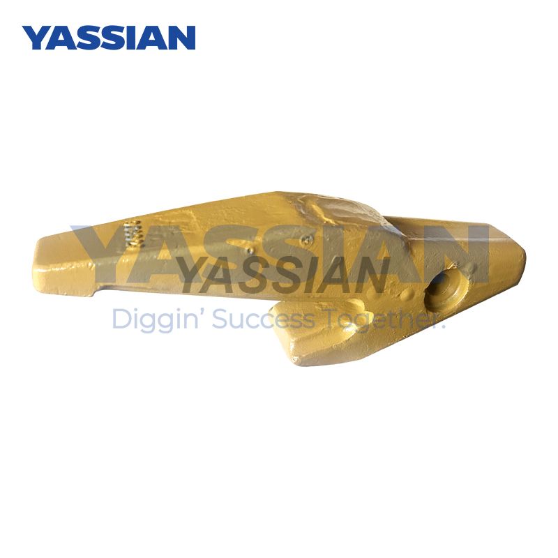


9J8929
YASSIAN


How to select the appropriate tool Angle based on the working conditions
The selection of tool angles based on working conditions requires a comprehensive consideration of material properties, processing stages, and equipment conditions. The core optimization strategies are as follows:
1. Material property matching Angle combination
Soft materials (aluminium alloy/wood)
Increasing the rake Angle (20° to 25°) reduces cutting resistance and improves surface finish.
The helical edge Angle (30°) improves the smoothness of chip removal and reduces entanglement and downtime.
Hard materials (quenched steel/titanium alloy)
Negative rake Angle (-5° to 0°) enhances the impact resistance of the cutting edge and prevents chipping.
The main relief Angle is reduced by (≤8°) to enhance the tool strength, in combination with zero relief Angle heat dissipation.
Composite materials/intermittent cutting
The negative cutting edge Angle (-5° to 0°) strengthens the cutting tip to resist impact loads.
Ii. Differentiated configuration in the processing stage
1. Rough machining (efficient removal of allowance)
Main deflection Angle 45° : Extend the participating length of the cutting edge to disperse the heat load.
The small rake Angle/relief Angle (rake Angle ≤6°, relief Angle 6° - 8°) ensures the strength of the cutting edge.
The radius of the arc at the large tool tip (R0.5-1mm) reduces local wear.
2. Fine processing (high surface quality
Principal deflection Angle ≥90° : reduces radial force and suppresses deformation of thin-walled parts (91° to 95° is recommended for optimal results).
Positive rake Angle + large relief Angle (rake Angle 25°, relief Angle 10° to 12°) reduces frictional resistance.
Secondary deflection Angle ≤5° : Polish the surface, increase the tool nose radius to R1 to 2mm.
Iii. Special Working Conditions Response Plan
Working conditions tool Angle scheme mechanism of action
Weak system rigidity main deflection Angle 75° to 90°+ vibration damping chamfering reduces the back force and suppresses flutter
High-speed cutting slightly reduces the relief Angle + the helical edge inclination Angle enhances the edge rigidity and stabilizes the feed
Deep cavity machining a large rake Angle (20°) + positive edge inclination Angle improves chip removal and avoids cutting blockage
Iv. Quick Reference Table of Practical Parameters
Recommended Angle combinations for target material types
High-efficiency rough turning castings cast iron negative rake Angle (-3°) + main deflection Angle 45°
Precision milled aluminum alloy aluminum alloy rake Angle 25°+ cutting edge inclination Angle 15°
Step surface turning alloy steel main deflection Angle 90°+ zero relief Angle edge surface
Note: The Angle range of the tool tip needs to match the allowance - for rough machining, select 34° to 44° to balance strength and sharpness, and for finish machining, use 14° to 20° to enhance the surface finish.


