 |


| Quantity: | |
|---|---|
|
| |
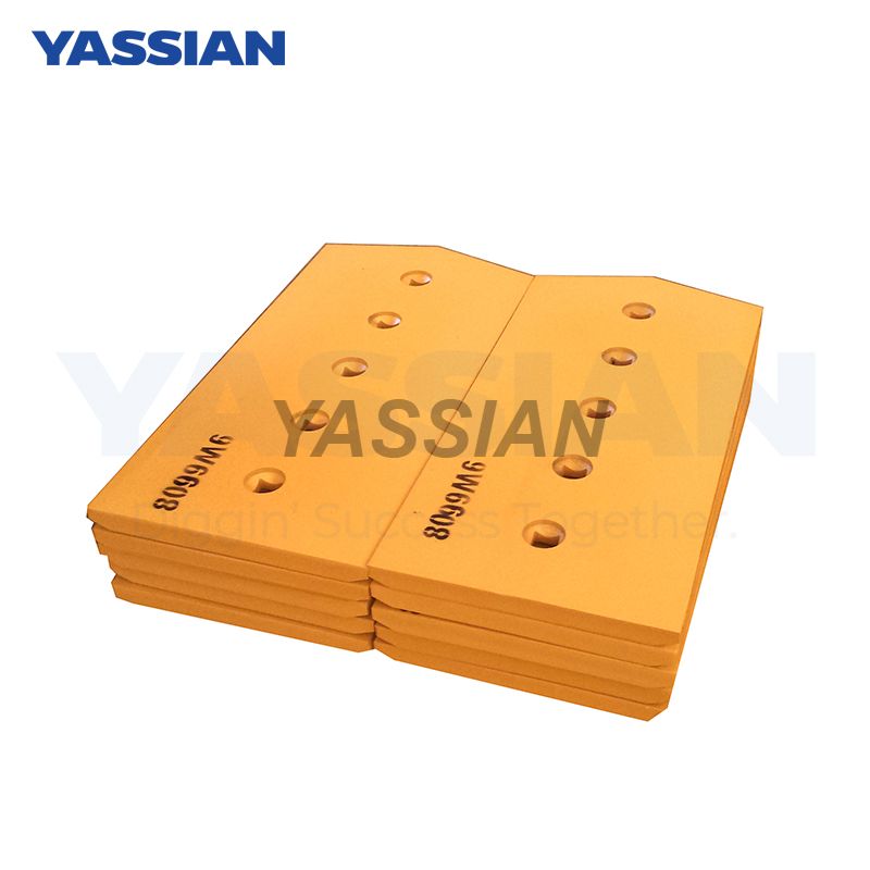
9W6608
YASSIAN or Your's


Testing Standard for Surface Roughness of Bucket Teeth in Construction Machinery
The following are the detection standards and technical key points for the surface roughness of bucket teeth in construction machinery, compiled based on current national standards and industry practices:
I. Definition of Core Parameters and Standard Requirements
Evaluation parameter priority
Contour arithmetic mean deviation (Ra) : preferred parameter, representing the arithmetic mean of the absolute values of contour offsets within the sampling length.
Maximum contour height (Rz) : A secondary parameter, indicating the distance between the peak line and the bottom line of the contour within the sampling length.
Ra limit for key parts of bucket teeth (GB/T 25628-2023 reference) :
Surface type Ra upper limit (μm) applicable area
The working surface of the tooth tip is ≤1.6. Main cutting edge and tooth tip strengthening layer
The transition zone at the tooth root ≤3.2 stress concentration zone at the tooth root fillet
Non-mating installation surface ≤12.5 tooth seat contact surface, bolt holes
Symbol marking specification
Remove the material symbol (⛶) : this symbol must be marked on the machined surface of the bucket tooth machine (such as milling the tooth seat and grinding the tooth tip).
Without removing the material symbol (◯) : the casting surface is directly used (such as the base surface of the unmachined tooth body).
Special marking : Different roughness levels on the same surface should be demarcated with fine solid lines.
Ii. Detection Methods and Operating Procedures
1. Contact roughness meter testing (laboratory standard)
Probe scanning : move uniformly along the normal direction of the tooth surface, with a sampling length of ≥0.8mm, and the evaluation length includes 5 sampling lengths.
Data processing : Automatically calculate Ra/Rz values to eliminate abnormal peaks caused by local pores or inclusions.
2. Comparison sample method (quick on-site determination)
Operation steps :
① Clean the tooth surface and select the roughness comparison template of the same processing method (Ra value 1.6μm/3.2μm/6.3μm);
② Compare the fingernail scraping sample with the tooth surface to feel the consistency of resistance.
Limitation : only applicable to surfaces with Ra≥1.6μm.
3. Light sectioning microscopy (for highly reflective surfaces)
Applicable scenarios : laser cladding of tooth tips (reflectivity > 70%).
Key operation : Adjust the Angle between the light bands of the double microscope, measure the spacing of the interference fringes and calculate the Rz value.
Iii. Failure Analysis and Control Measures
Defect type roughness correlation influence improvement scheme
Early wear with Ra > 1.6μm intensifies the embedding of abrasive grains into fine grinding followed by shot peening treatment (reducing Ra by 0.2 grade)
Fatigue crack Rz exceeding the standard leads to stress concentration. The root fillet is polished to Ra≤3.2μm
The loose installation surface Ra is greater than 12.5μm to reduce friction. Milling processing ensures Ra≤6.3μm
Note : For the inspection of worn bucket teeth, avoid pits with a depth greater than 0.5mm and take samples from the intact edge area.
Iv. Standards for Remanufacturing Used parts
The surface of the cladding layer : after laser cladding repair, Ra should be ≤6.3μm (higher than the allowable value of the substrate).
Local over-limit handling : 10% of the measurement points are allowed to have Ra exceed the limit, but the over-limit value must not exceed 50% of the standard value.


